Pass CompTIA Network+ Certification Exam in First Attempt Guaranteed!
Get 100% Latest Exam Questions, Accurate & Verified Answers to Pass the Actual Exam!
30 Days Free Updates, Instant Download!


N10-009 Premium Bundle
- Premium File 724 Questions & Answers. Last update: Jul 07, 2026
- Training Course 240 Video Lectures
- Study Guide 128 Pages
N10-009 Premium Bundle
- Premium File 724 Questions & Answers
Last update: Jul 07, 2026 - Training Course 240 Video Lectures
- Study Guide 128 Pages
Purchase Individually

Premium File
Training Course

Study Guide
N10-009 Exam - CompTIA Network+
| Download Free N10-009 Exam Questions |
|---|
CompTIA CompTIA Network+ Certification Practice Test Questions and Answers, CompTIA CompTIA Network+ Certification Exam Dumps
All CompTIA CompTIA Network+ certification exam dumps, study guide, training courses are prepared by industry experts. CompTIA CompTIA Network+ certification practice test questions and answers, exam dumps, study guide and training courses help candidates to study and pass hassle-free!
Foundations of the CompTIA Network+ Certification
CompTIA, the Computing Technology Industry Association, stands as a cornerstone in the world of information technology education and certification. It is a non-profit trade association that has established itself as a leading provider of professional certifications for the IT industry. Unlike certifications offered by specific technology companies, CompTIA credentials are vendor-neutral. This means the knowledge and skills they validate are not tied to a single product or platform. This neutrality is a significant advantage for IT professionals, providing them with a foundational understanding of concepts that are applicable across a wide array of hardware and software environments.
The philosophy behind vendor-neutral certifications is to build a conceptual framework that professionals can apply anywhere. Whether an organization uses Cisco, Juniper, or Aruba networking equipment, the fundamental principles of networking remain the same. CompTIA focuses on these universal principles, ensuring that a certified individual understands how networks operate at a core level. This approach fosters adaptability and critical thinking, which are highly valued by employers. It equips professionals with a versatile skill set, making them valuable assets in a diverse and ever-changing technological landscape, rather than specialists in a single proprietary ecosystem that may become obsolete.
The Network+ certification is a prime example of this philosophy in action. It is designed to be the first networking-specific credential for an IT professional who wants to build a career in network administration and support. It validates the essential knowledge required to confidently design, configure, manage, and troubleshoot both wired and wireless networks. By earning this certification, you signal to the industry that you possess a comprehensive understanding of networking technologies and are ready to take on roles that require a strong, universally applicable foundation in the field.
Why the Network+ Certification Matters in Today's IT Landscape
In an increasingly connected world, network infrastructure is the backbone of virtually every business operation. From small offices to multinational corporations, reliable and secure networks are not just a convenience; they are a critical necessity. The CompTIA Network+ certification directly addresses this need by validating the skills required to maintain these vital systems. Employers recognize the Network+ credential as a benchmark for foundational networking proficiency. It assures them that a candidate understands the complexities of network infrastructure, from initial setup to ongoing maintenance and troubleshooting, which reduces risk and hiring uncertainty.
This certification is particularly relevant because it is regularly updated to reflect the current state of networking technology. The IT industry evolves at a breathtaking pace, and a certification that fails to keep up quickly loses its value. CompTIA periodically revises the Network+ exam objectives to include modern topics such as cloud networking, virtualization, and the latest security protocols. This commitment to relevance ensures that certified professionals are equipped with up-to-date knowledge, making them more competitive in the job market and more effective in their roles. It demonstrates a proactive commitment to professional development.
Furthermore, the Network+ certification often serves as a prerequisite or a stepping stone to more advanced, specialized, and often vendor-specific certifications. Many professionals who earn their Network+ go on to pursue credentials like the Cisco Certified Network Associate (CCNA) or advanced security certifications. The foundational knowledge gained from the Network+ curriculum provides the necessary context and vocabulary to tackle these more complex subjects. It builds the solid ground upon which a successful and specialized IT career can be constructed, opening doors to higher-level roles and greater earning potential over time.
Target Audience: Who Should Pursue the Network+?
The CompTIA Network+ certification is ideally suited for individuals who have already gained some foundational IT knowledge, perhaps through experience or by earning the CompTIA A+ certification. While there are no strict official prerequisites, a basic understanding of computer hardware, software, and operating systems is highly recommended. The exam is not designed to introduce someone to the IT field from scratch; rather, it is intended to help those already in the field specialize in networking. It is perfect for help desk technicians, junior system administrators, or anyone in a general IT support role looking to pivot towards a more network-focused career path.
This certification is also highly beneficial for those aiming for specific job roles where networking is a primary responsibility. Aspiring network administrators, network support specialists, junior network engineers, and NOC technicians will find the Network+ curriculum directly aligns with the skills required for these positions. The content covers the day-to-day tasks these professionals encounter, such as configuring routers and switches, managing IP addresses, and troubleshooting connectivity issues. It provides the vocabulary and practical knowledge needed to communicate effectively with senior network engineers and to perform essential job functions with confidence from day one.
Even professionals in adjacent IT fields can benefit from the Network+ certification. For example, cybersecurity analysts need to understand networks to identify and mitigate threats. Cloud engineers must have a firm grasp of networking to manage virtualized network resources and ensure connectivity to cloud services. The Network+ provides a comprehensive overview that is valuable for any IT professional whose work intersects with network infrastructure. It broadens their skill set, makes them more versatile, and allows them to better understand how their specific role fits into the larger IT ecosystem of an organization.
Exploring the Core Networking Models: OSI and TCP/IP
At the heart of the CompTIA Network+ curriculum are the two most important networking models: the Open Systems Interconnection (OSI) model and the Transmission Control Protocol/Internet Protocol (TCP/IP) model. These models are not physical technologies but conceptual frameworks used to standardize the functions of a telecommunication or computing system in layers. Understanding these models is non-negotiable for any networking professional, as they provide a common language and a structured way to think about how data travels from one device to another across a network.
The OSI model is a seven-layer framework that provides a detailed, granular view of the networking process. The layers, from bottom to top, are Physical, Data Link, Network, Transport, Session, Presentation, and Application. Each layer performs a specific function and only interacts with the layers directly above and below it. For example, the Physical layer deals with the actual hardware, like cables and electrical signals, while the Application layer provides network services directly to the end-user's applications. This model is invaluable for troubleshooting because it allows professionals to systematically isolate problems layer by layer.
The TCP/IP model, also known as the Internet Protocol suite, is a more practical and widely implemented four-layer model. Its layers are Network Interface (or Link), Internet, Transport, and Application. This model is less theoretical than the OSI model and corresponds more directly to the protocols that run the modern internet. For the Network+ exam, you will need to understand how the layers of the TCP/IP model map to the layers of the OSI model. For example, the TCP/IP Application layer encompasses the functions of the OSI's Application, Presentation, and Session layers.
A deep understanding of both models is crucial for success. You will be expected to know the purpose of each layer, the key protocols that operate at each layer (such as Ethernet at the Data Link layer, IP at the Network layer, and TCP/UDP at the Transport layer), and how to use the models as a diagnostic tool. When a user reports they cannot access a website, a skilled technician mentally works through the layers to pinpoint the cause, checking everything from the physical cable connection to the IP address configuration and DNS resolution at the application level.
Fundamentals of IP Addressing and Subnetting
One of the most challenging yet critical domains within the Network+ certification is IP addressing and the related concept of subnetting. An Internet Protocol (IP) address is a unique numerical label assigned to each device connected to a computer network that uses the Internet Protocol for communication. This address serves two main functions: host or network interface identification and location addressing. The most common version today is IPv4, which uses a 32-bit address, while the newer IPv6 standard uses a 128-bit address to accommodate the vast and growing number of devices connecting to the internet.
The Network+ exam places a heavy emphasis on understanding IPv4 addressing, including the different classes of addresses (A, B, C, D, and E), private versus public IP addresses, and the purpose of special addresses like the loopback address (127.0.0.1). You will need to be comfortable with binary-to-decimal conversion, as IP addresses are represented in dotted-decimal notation for human readability but are fundamentally binary numbers. This foundational knowledge is essential before you can tackle the more complex topic of subnetting.
Subnetting is the process of dividing a single, large network into smaller, more manageable sub-networks, or subnets. This is done for several reasons, including improving network performance by reducing broadcast traffic, enhancing security by isolating different parts of the network, and simplifying administration. To subnet a network, a network administrator borrows bits from the host portion of the IP address and uses them to create a subnet identifier. This process requires a solid understanding of subnet masks and CIDR (Classless Inter-Domain Routing) notation.
For the exam, you will likely encounter performance-based questions that require you to perform subnetting calculations. You might be given a network address and a set of requirements, such as the number of subnets needed or the number of hosts required per subnet, and you will have to determine the appropriate subnet mask, the range of usable IP addresses for each subnet, and the broadcast address. Mastering subnetting takes practice, but it is a fundamental skill that demonstrates a true understanding of how IP networks are structured and managed efficiently.
An Overview of Common Network Devices
The CompTIA Network+ exam requires a thorough understanding of the various hardware devices that form the building blocks of any network. These devices operate at different layers of the OSI model and perform distinct functions to ensure data gets from its source to its destination correctly and efficiently. A foundational device is the hub, which operates at the Physical layer (Layer 1). A hub is a simple device that receives a signal on one port and regenerates it out to all other ports. It is an older technology largely replaced by switches because it creates a single collision domain, leading to inefficient network performance.
Switches are a significant improvement over hubs and operate at the Data Link layer (Layer 2). Unlike a hub, a switch is intelligent. It can read the MAC (Media Access Control) address of the destination device contained in a data frame and forward that frame only to the specific port connected to that destination device. This process, known as microsegmentation, creates separate collision domains for each port, drastically reducing network congestion and improving overall performance. Network+ candidates must understand how switches learn MAC addresses and populate their MAC address table.
Routers are essential devices that operate at the Network layer (Layer 3). The primary function of a router is to connect different networks together and make decisions about the best path for data to travel between them. While a switch uses MAC addresses to forward data within a single local network (LAN), a router uses IP addresses to forward data packets between different networks, such as connecting your home network to the internet. Understanding routing tables and the basics of routing protocols is a key objective for the exam.
Other important devices covered in the curriculum include firewalls, which are security devices that monitor and control incoming and outgoing network traffic based on predetermined security rules. Access Points (APs) are used to create wireless local area networks (WLANs). Modems (modulator-demodulators) are used to connect a local network to an Internet Service Provider (ISP) over different types of media, like cable or DSL. A solid grasp of what each device does, where it operates in the OSI model, and how it contributes to the overall function of the network is fundamental for any aspiring network professional.
Wired Networking: Cabling and Connectors
A fundamental aspect of network infrastructure is the physical medium used to transmit data, and for wired networks, this means understanding various types of cables and their corresponding connectors. The CompTIA Network+ exam dedicates a significant portion of its objectives to this topic, as improper cabling is a common source of network problems. The most prevalent type of cabling in local area networks (LANs) is twisted-pair copper cabling. This includes Unshielded Twisted Pair (UTP) and Shielded Twisted Pair (STP). You will need to know the different categories, such as Cat5e, Cat6, and Cat6a, and understand their differences in terms of bandwidth capacity and resistance to interference.
For each category of twisted-pair cable, you must be familiar with the connector it uses, which is typically the RJ-45 connector. This involves not only identifying the connector but also understanding the T568A and T568B wiring standards. These standards define the pinout, or the specific order in which the eight individual wires within the cable are terminated. Knowing the difference between a straight-through cable (which uses the same standard on both ends) and a crossover cable (which uses T568A on one end and T568B on the other) and their specific use cases is a critical piece of knowledge.
Beyond copper cabling, the exam also covers coaxial and fiber optic cables. Coaxial cable, while less common in modern LANs, is still widely used by cable internet providers. You should be able to identify its components and the common connectors it uses, such as the BNC connector or the F-connector. Fiber optic cable is the standard for high-speed, long-distance data transmission. It transmits data using pulses of light and is immune to electromagnetic interference. You will need to differentiate between single-mode fiber (SMF) for long distances and multi-mode fiber (MMF) for shorter distances, as well as recognize common fiber connectors like LC, ST, and SC.
Understanding the properties of these cabling solutions is also essential. This includes concepts like attenuation (the weakening of a signal over distance), crosstalk (interference between adjacent wires), and the maximum transmission distance for each cable type. A network professional must be able to select the appropriate cable for a given scenario, properly terminate it, and diagnose issues related to the physical cabling. These hands-on skills are often tested through performance-based questions where you might be asked to identify a cable type or match a connector to its cable.
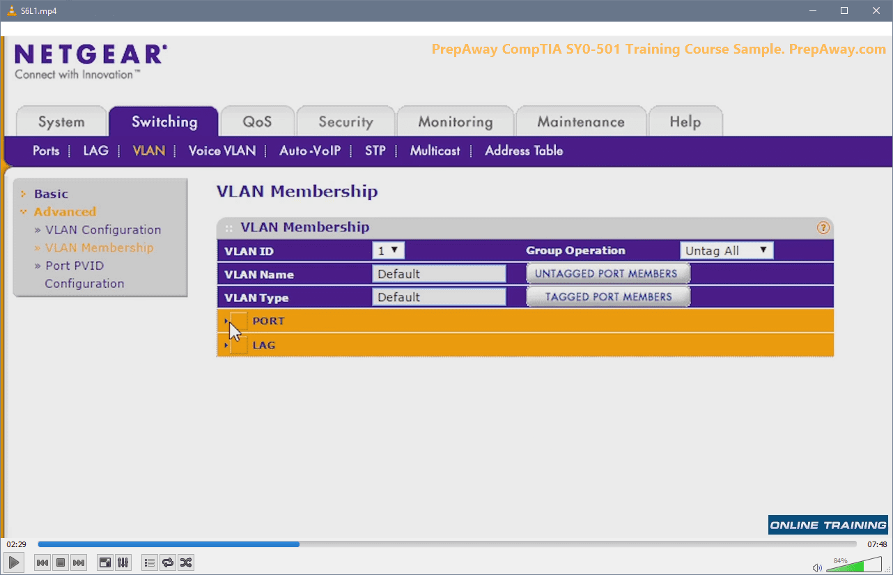
Configuring and Managing Switched Networks
Switches are the core of most modern local area networks, and the ability to configure and manage them is a vital skill for any network technician. The Network+ exam moves beyond simply identifying a switch and requires you to understand its advanced features and configuration. One of the most important concepts is the Virtual LAN, or VLAN. VLANs allow a network administrator to segment a single physical switch into multiple separate virtual networks. This is done to improve security, manage traffic, and increase performance by isolating broadcast domains. You must understand how to create VLANs and assign ports to them.
Another key topic is the Spanning Tree Protocol (STP). In switched networks, it is common to create redundant links between switches to provide fault tolerance. However, these redundant links can create switching loops, which cause broadcast storms that can bring down the entire network. STP is a protocol that prevents these loops by intelligently blocking redundant paths. It ensures there is only one active path between any two points on the network at any given time, while keeping the blocked paths in a standby state, ready to be activated if the primary path fails. You need to know the purpose of STP and its different states.
Security is also a major consideration in switch management. Port security is a feature that allows an administrator to restrict access to a switch port based on the MAC address of the device connected to it. You can configure a port to allow only a specific MAC address, or a certain number of MAC addresses, to connect. If an unauthorized device is plugged in, the port can be configured to shut down or simply drop the traffic. This is a fundamental security measure to prevent unauthorized access to the network. Familiarity with commands to configure port security is highly beneficial.
Finally, you should understand concepts related to switch performance and management, such as link aggregation. Link aggregation, often implemented using the Link Aggregation Control Protocol (LACP), allows you to combine multiple physical ports into a single logical channel. This increases the available bandwidth between two devices, such as between two switches or a switch and a server, and also provides redundancy. Additionally, you should know about port mirroring, which is used to copy traffic from one port to another for monitoring and analysis purposes. These features are central to building a robust and manageable switched network.
Implementing and Troubleshooting Wireless Technologies
Wireless networking has become ubiquitous, and a comprehensive understanding of wireless technologies is a critical component of the CompTIA Network+ certification. The exam covers the various IEEE 802.11 standards, such as 802.11a, 802.11b/g/n, 802.11ac (Wi-Fi 5), and 802.11ax (Wi-Fi 6). For each standard, you need to know the frequency band it operates on (2.4 GHz or 5 GHz), its maximum data rate, and its key features. Understanding the pros and cons of each frequency band, such as the longer range of 2.4 GHz versus the higher speed and less interference of 5 GHz, is essential.
Setting up a secure and efficient wireless network requires knowledge of several key concepts. You must understand the different wireless security protocols, including the outdated and insecure WEP (Wired Equivalent Privacy), the improved WPA (Wi-Fi Protected Access), and the current standard, WPA2, which uses AES encryption. The even more recent WPA3 standard offers further security enhancements. You should be able to configure a wireless access point (AP) with the appropriate SSID (Service Set Identifier), security protocol, and passphrase.
Proper implementation also involves careful planning of AP placement. A site survey is often conducted to identify the optimal locations for APs to ensure adequate coverage and minimize interference. You should be familiar with factors that can affect wireless signals, such as building materials, and sources of interference, like microwave ovens or cordless phones. Concepts like channel selection are important; in the 2.4 GHz band, using non-overlapping channels (1, 6, and 11) is a best practice to reduce co-channel interference between nearby APs.
Troubleshooting wireless issues is a common task for network technicians. Problems often manifest as slow speeds, intermittent connectivity, or the inability to connect at all. You should be ableto diagnose these issues using various tools and techniques. This could involve checking for signal strength issues, identifying sources of radio frequency interference using a spectrum analyzer, or ensuring that the client device has the correct configuration and security credentials. Understanding common problems like mismatched security settings or incorrect channel configurations is key to passing the exam and succeeding in the field.
Routing Fundamentals: Connecting Networks
While switches operate within a single local network, routers are the devices that connect different networks together. The CompTIA Network+ exam requires a solid understanding of the fundamental principles of routing. At its core, routing is the process of selecting a path for traffic in a network or between multiple networks. This decision-making process is handled by routers, which use routing tables to determine the best path to forward a packet to its destination IP address. You must understand the structure of a routing table and how a router uses it to make forwarding decisions.
There are two primary ways a router can learn about routes: static routing and dynamic routing. With static routing, a network administrator manually configures all routes in the routing table. This method is simple and secure but is not scalable. It is only suitable for very small, simple networks because any change in the network topology requires manual updates. If a link goes down, the router has no way to automatically find an alternative path.
Dynamic routing, on the other hand, involves the use of routing protocols. These protocols allow routers to automatically learn about other networks and share this information with their neighbors. When a change occurs in the network, such as a link failure, the routers can automatically recalculate new paths and update their routing tables accordingly. The Network+ exam expects you to be familiar with the different types of dynamic routing protocols. These are categorized into Interior Gateway Protocols (IGPs), used within a single autonomous system, and Exterior Gateway Protocols (EGPs), used between different autonomous systems.
Within the IGP category, you should know the difference between distance-vector protocols (like RIP) and link-state protocols (like OSPF). Distance-vector protocols make routing decisions based on the number of hops (routers) to a destination, while link-state protocols have a complete map of the network topology and make more intelligent decisions based on factors like link speed. While you are not expected to master the complex configuration of these protocols, you must understand their purpose, their basic characteristics, and how they enable the creation of scalable and resilient networks.
Understanding Network Operations and Management
Beyond the technical implementation of hardware and protocols, the CompTIA Network+ certification emphasizes the importance of effective network operations and management. This domain covers the practices and procedures that ensure a network remains reliable, secure, and efficient over time. A crucial aspect of this is network documentation. Maintaining accurate and up-to-date documentation is vital for troubleshooting, planning, and administration. This includes creating network diagrams (both physical and logical), maintaining IP address schemas, and documenting device configurations. Proper documentation saves invaluable time when problems arise or when changes need to be made.
Network monitoring is another critical operational task. Proactive monitoring allows administrators to identify potential issues before they impact users. You should be familiar with monitoring protocols like SNMP (Simple Network Management Protocol), which is used to collect information from network devices and monitor their health. Understanding log management is also important. Network devices generate logs that contain a wealth of information about events, errors, and security incidents. Knowing how to access, centralize, and analyze these logs is a key skill for diagnosing problems and performing security audits.
Establishing baselines is a core concept in network performance management. A performance baseline is a set of metrics that represents the normal, satisfactory operation of the network. This includes measurements of bandwidth utilization, latency, and error rates. By establishing a baseline, administrators have a reference point to compare against when performance issues are reported. A sudden deviation from the baseline can indicate a problem that needs investigation. The exam will expect you to understand the importance of baselines and the types of metrics that should be tracked.
Finally, you should be familiar with organizational policies and best practices related to network management. This includes things like change management procedures, which provide a structured process for implementing changes to the network to minimize disruption. It also covers concepts like disaster recovery planning, which involves creating strategies to restore network services in the event of a major outage. These operational aspects are just as important as the technical configurations, as they contribute to the overall stability and business continuity of the organization.
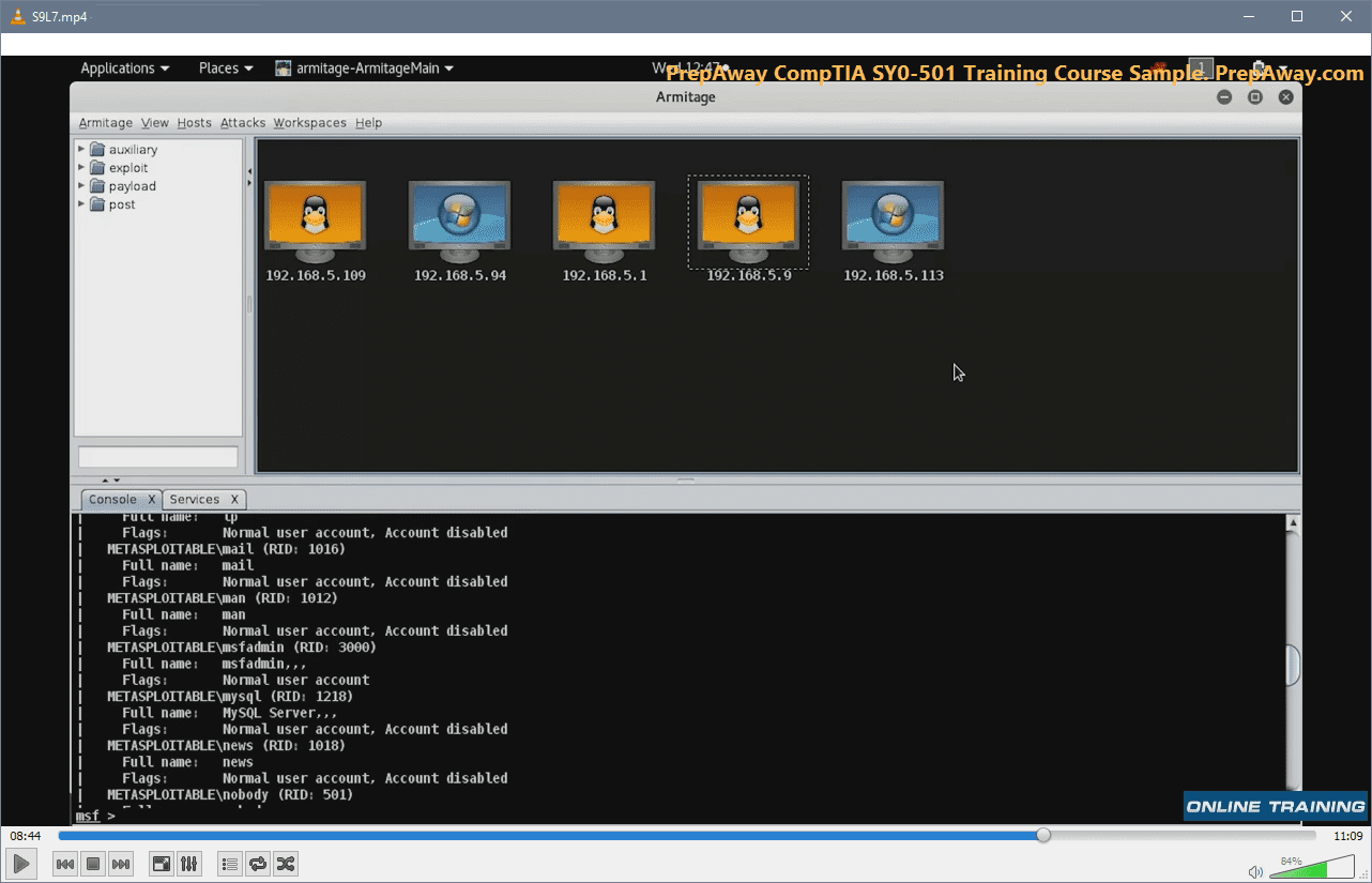
Identifying and Mitigating Common Network Attacks
In today's digital environment, network security is paramount, and the CompTIA Network+ exam places a strong emphasis on it. A core part of this domain is the ability to identify common types of network attacks and understand how to mitigate them. One of the most prevalent threats is a Denial-of-Service (DoS) attack, or its more potent variant, the Distributed Denial-of-Service (DDoS) attack. The goal of these attacks is to overwhelm a server or network with traffic, rendering it unavailable to legitimate users. Mitigation often involves traffic filtering, using a content delivery network, and working with an ISP to block malicious traffic.
Another category of attack involves social engineering, where an attacker manipulates individuals into divulging confidential information or performing actions that compromise security. Phishing is a common example, where deceptive emails are used to trick users into revealing login credentials or financial information. Mitigation for these attacks is less about technology and more about user education and awareness training. Policies that enforce strong password requirements and the use of multi-factor authentication also play a crucial role in limiting the damage from a successful phishing attempt.
You also need to be familiar with attacks that target specific network protocols and devices. For instance, a MAC spoofing attack involves an attacker altering the MAC address of their device to impersonate a legitimate device on the network. This can be used to bypass access control lists or to intercept traffic. An ARP poisoning attack corrupts the ARP cache on a network, allowing an attacker to redirect traffic through their own machine, leading to a man-in-the-middle attack where they can eavesdrop on or alter communications. Mitigation techniques for these include using port security on switches and implementing dynamic ARP inspection.
Understanding malware is also essential. This includes viruses, worms, trojans, and ransomware. While often thought of in the context of individual computers, malware can have devastating effects on a network, spreading rapidly from one device to another. Network-level defenses are critical for mitigation. This includes using firewalls with advanced threat protection, deploying network-based intrusion detection and prevention systems (IDS/IPS), and ensuring all systems are kept up-to-date with the latest security patches. A layered security approach, often called defense in depth, is the most effective strategy.
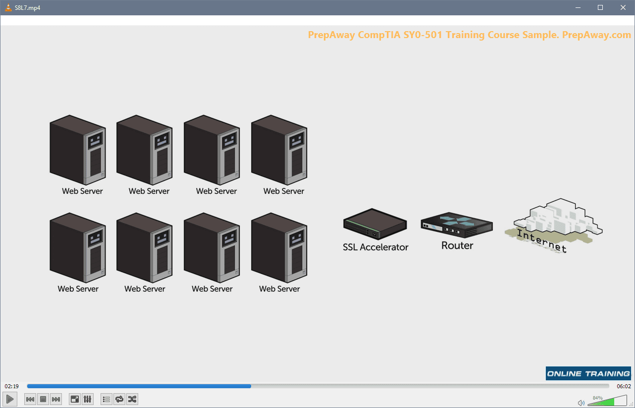
Implementing Security Devices and Technologies
To defend against the myriad of threats, network professionals must know how to properly deploy and configure various security devices and technologies. The most fundamental of these is the firewall. A firewall acts as a barrier between a trusted internal network and an untrusted external network, such as the internet. You need to understand the difference between different types of firewalls, such as stateless packet-filtering firewalls and stateful firewalls, which track the state of active connections. Modern next-generation firewalls (NGFWs) offer even more advanced features, including deep packet inspection and integrated intrusion prevention systems.
Intrusion Detection Systems (IDS) and Intrusion Prevention Systems (IPS) are another critical layer of defense. An IDS is a passive device that monitors network traffic for suspicious activity and generates an alert if a potential threat is detected. An IPS is an active device that goes a step further; in addition to detecting threats, it can take action to block the malicious traffic before it reaches its target. The Network+ exam expects you to know the difference between these two systems and understand common placement strategies, such as placing them at the network edge or on critical network segments.
Access Control Lists (ACLs) are a fundamental tool for controlling traffic flow. An ACL is a set of rules, typically applied to a router or firewall interface, that specifies what traffic is allowed to pass and what traffic is denied. The rules can be based on various criteria, such as source and destination IP addresses, port numbers, and the protocol being used. You should understand the basic syntax of an ACL and the importance of the implicit "deny all" rule that is typically found at the end of every list. Proper ACL configuration is key to enforcing security policies on the network.
Another important security technology is the Virtual Private Network (VPN). A VPN creates a secure, encrypted tunnel over an untrusted network, like the internet, allowing for secure remote access to an organization's internal resources. You should be familiar with the key protocols used for VPNs, such as IPsec and SSL/TLS, and understand the difference between a site-to-site VPN, which connects two entire networks, and a remote-access VPN, which connects an individual user to a network. VPNs are essential for securing data in transit and supporting a remote workforce.
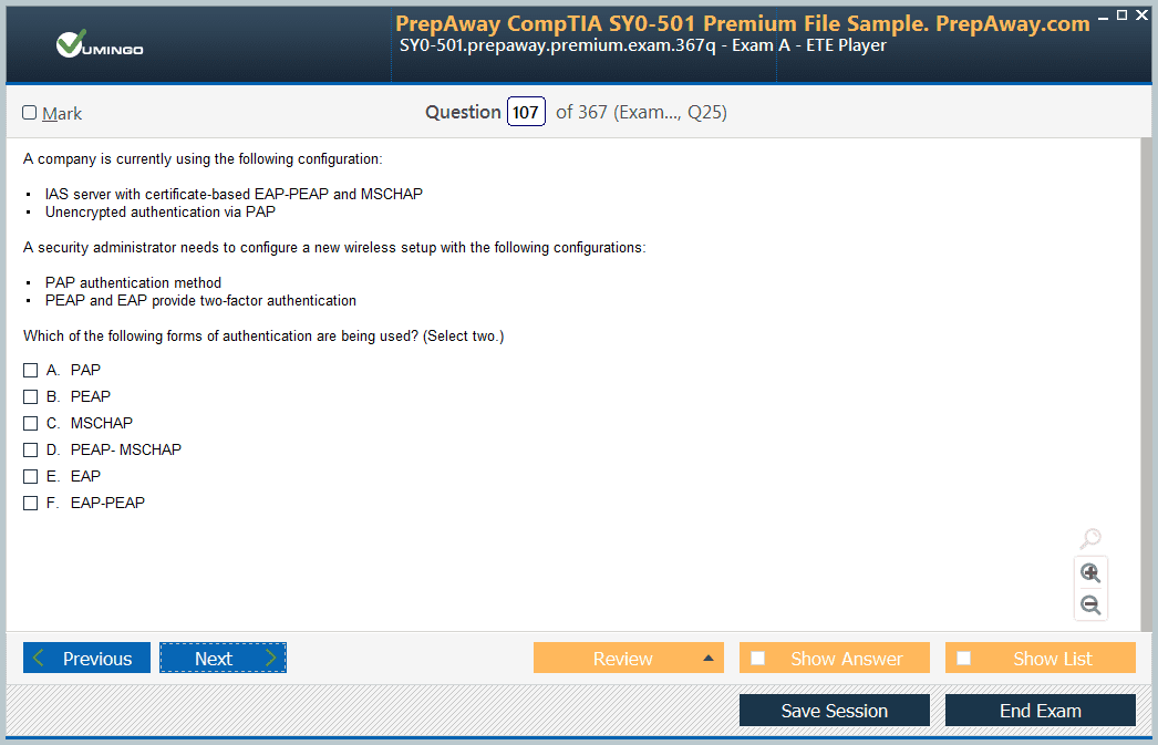
Authentication, Authorization, and Access Control
A robust security posture relies on ensuring that only authorized individuals can access network resources. This is achieved through the principles of authentication, authorization, and access control. Authentication is the process of verifying a user's identity. This is most commonly done with a username and password, but this method has weaknesses. The Network+ curriculum introduces the concept of multi-factor authentication (MFA), which provides much stronger security by requiring a user to provide two or more different types of verification before being granted access. These factors are something you know (password), something you have (a token or smartphone), or something you are (a fingerprint or face scan).
Once a user has been authenticated, the next step is authorization. Authorization is the process of determining what an authenticated user is allowed to do. This is based on the principle of least privilege, which dictates that a user should only be granted the minimum level of access and permissions necessary to perform their job functions. For example, a user in the finance department should be authorized to access the accounting server but should not be authorized to access the servers managed by the IT department. This helps to contain the damage if a user's account is ever compromised.
Access control is the mechanism by which these authentication and authorization policies are enforced. There are various models for access control, such as Role-Based Access Control (RBAC), where permissions are assigned to specific job roles rather than to individual users. This simplifies administration, as users can be easily moved between roles. You should also be familiar with network access control (NAC) solutions. NAC can check the security posture of a device before it is allowed to connect to the network. For example, it can verify that the device has up-to-date antivirus software and the latest operating system patches installed.
To manage authentication and authorization in a centralized way, many organizations use services like RADIUS (Remote Authentication Dial-In User Service) or TACACS+ (Terminal Access Controller Access-Control System Plus). These protocols allow network devices, such as routers, switches, and VPN concentrators, to delegate the authentication process to a central server. This provides a single point of administration for user accounts and access policies, which is much more efficient and secure than configuring individual user accounts on every device. Understanding the role of these AAA (Authentication, Authorization, and Accounting) servers is an important exam objective.
The Structured Troubleshooting Methodology
One of the most valuable skills for a network professional is the ability to troubleshoot problems effectively and efficiently. Randomly trying different solutions is time-consuming and often makes the problem worse. The CompTIA Network+ exam emphasizes a structured troubleshooting methodology that provides a systematic approach to problem-solving. This methodology ensures that you work logically from one step to the next, documenting your findings along the way, until you reach a resolution. Following a consistent process is the hallmark of a skilled technician.
The first step in the methodology is to identify the problem. This involves gathering as much information as possible from the user and from any available monitoring systems. You need to question the user to understand the scope of the problem: who is affected, what are the specific symptoms, and when did the problem start? You should also check logs and system alerts. After gathering information, you should, if possible, replicate the problem yourself to confirm its existence and characteristics. A clear and accurate problem definition is the foundation for a successful resolution.
The second step is to establish a theory of probable cause. Based on the information you have gathered, you should start to form hypotheses about what might be causing the issue. This is where your technical knowledge comes into play. You might start by questioning the most obvious and simple potential causes before moving on to more complex ones. For example, if a single user cannot access the internet, a simple probable cause is that their network cable is unplugged. It is important to consider all possibilities and list them out.
Once you have a theory, the third step is to test it to determine the cause. If your theory is that the network cable is unplugged, the test is to check the cable. If the test confirms your theory, you have found the cause. If it does not, you must move on to your next theory and test that one. This is an iterative process. If none of your initial theories prove correct, you may need to escalate the issue to a more senior technician. This systematic approach prevents you from making random changes and helps you to logically narrow down the possibilities.
After you have identified the cause, the next steps are to establish a plan of action to resolve the problem and implement the solution. Once the solution is implemented, the final and crucial steps are to verify full system functionality and, if applicable, implement preventative measures to stop the problem from happening again. The last step is to document your findings, the actions you took, and the outcome. This documentation is invaluable for future reference and for building a knowledge base that can help other technicians solve similar problems more quickly.
Common Network Troubleshooting Tools
To effectively implement the troubleshooting methodology, you need to be proficient with a variety of hardware and software tools. The CompTIA Network+ exam will expect you to know what these tools are and when to use them. For physical layer issues, tools like a cable tester are essential for verifying the integrity of a network cable and ensuring it is terminated correctly. A tone generator and probe can be used to trace a specific cable through a bundle of wires in a wiring closet. A loopback plug is a simple device used to test a network interface card to ensure it is sending and receiving signals correctly.
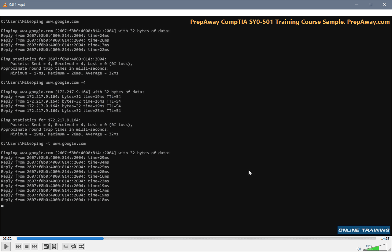
For issues at the data link and network layers, command-line utilities are your best friend. The ping command is one of the most basic and useful tools. It sends an ICMP echo request to a target IP address and waits for a reply, which allows you to test basic connectivity and measure latency. The ipconfig (on Windows) or ifconfig/ip (on Linux) commands are used to view and manage the IP address configuration of a local machine. The arp command allows you to view and manage the ARP cache, which maps IP addresses to MAC addresses.
When you need to trace the path that network traffic takes to a destination, the tracert (on Windows) or traceroute (on Linux) command is invaluable. It shows you every router (hop) that a packet passes through on its way to the destination, which can help you pinpoint where a communication failure is occurring. The nslookup and dig commands are used to query the Domain Name System (DNS) to resolve domain names to IP addresses and diagnose DNS-related problems.
For more in-depth analysis, a protocol analyzer, also known as a packet sniffer, is an essential tool. Software like Wireshark can capture all the traffic flowing across a network interface and allow you to inspect the individual packets in detail. This provides an unparalleled level of insight into what is happening on the network and is incredibly useful for diagnosing complex application-level problems or identifying suspicious security activity. Proficiency with these tools is a practical skill that separates an experienced technician from a novice.
Crafting a Personalized Study Plan
Preparing for the CompTIA Network+ exam requires a structured approach, and the foundation of that approach is a personalized study plan. Simply reading a book from cover to cover is often not the most effective strategy. A good study plan should be tailored to your existing knowledge, your preferred learning style, and the amount of time you can realistically dedicate each week. The first step is to download the official exam objectives from the CompTIA website. This document is your roadmap; it details every topic and sub-topic that could appear on the exam.
Once you have the objectives, perform a self-assessment. Go through the list and rate your confidence level for each item. You might be very comfortable with basic IP addressing but have little to no knowledge of wireless security protocols. This assessment will help you identify your weak areas, which is where you should focus the majority of your study time. Your plan should allocate more time to these challenging topics and less time to the concepts you already understand well. This targeted approach is far more efficient than giving equal time to every subject.
Next, you need to set a realistic timeline. The average candidate spends between 10 to 12 weeks studying, but this can vary significantly based on prior experience. If you are working full-time, you might only be able to dedicate an hour or two each day. Be honest with yourself about your schedule and commitments. Break down your study plan into manageable weekly and daily goals. For example, one week might be dedicated to mastering the OSI model, while the next focuses entirely on subnetting practice. A detailed schedule helps to maintain momentum and prevent cramming.
Your study plan should also incorporate different learning methods to keep you engaged. Don't just rely on one resource. Plan to read a chapter from a study guide, then watch a corresponding video course on the topic, and then finish with some hands-on lab exercises. Spacing out your studying and revisiting topics periodically, a technique known as spaced repetition, is also highly effective for long-term retention. Regularly review your plan and adjust it as needed. If you master a topic faster than expected, you can reallocate that time to an area where you are struggling.
Choosing the Right Study Materials
The market is filled with study materials for the CompTIA Network+ exam, and choosing the right combination of resources is crucial for success. It is generally recommended to use a primary study guide as the core of your preparation. Look for official CompTIA materials or well-regarded third-party books from reputable publishers. A good study guide will be comprehensive, well-structured, and closely aligned with the latest exam objectives. It will serve as your main reference text, providing detailed explanations of all the required concepts.
While a study guide is essential, it should be supplemented with other resources to cater to different learning styles. Video courses are an excellent way to learn, as a good instructor can explain complex topics in an engaging and easy-to-understand manner. Many platforms offer on-demand video training that allows you to learn at your own pace. These courses often include demonstrations and real-world examples that can make abstract concepts, like routing protocols, much clearer than just reading about them in a book.
Practice exams are an absolutely indispensable part of your preparation. They serve two main purposes. First, they help you to assess your knowledge and identify any remaining weak spots that need further review. Second, they help you get comfortable with the format and style of the questions on the actual exam, including the performance-based questions. Look for practice tests that provide detailed explanations for both correct and incorrect answers. Simply knowing you got a question wrong is not enough; you need to understand why your answer was wrong and why the correct answer is right.
Finally, do not underestimate the importance of hands-on experience. Theoretical knowledge is important, but the Network+ exam also tests your ability to apply that knowledge in practical scenarios. If you do not have access to real networking equipment, you can use lab simulators or build a virtual lab using software like GNS3 or EVE-NG. These tools allow you to create virtual networks with routers and switches, giving you a safe environment to practice configuration and troubleshooting commands. This practical application is what solidifies your understanding and prepares you for the performance-based questions on the exam.
CompTIA Network+ certification practice test questions and answers, training course, study guide are uploaded in ETE files format by real users. Study and pass CompTIA CompTIA Network+ certification exam dumps & practice test questions and answers are the best available resource to help students pass at the first attempt.


Anyone who has recently written N+ (N10-006) , are these dumps are valid? I've just finished reading the book i need something i can prepare with for exam.
Thank you in advance.